Ballast
The operation of fluorescent lamps requires a control gear, which regulates the amount of electricity that flow to the lamp. The control gear used in fluorescent lamps is called ballast. The energy efficient technologies regarding ballast applications are described in this section.
Electronic ballast
There two main kinds of ballast namely magnetic ballast and electronic ballast. Magnetic ballast has been developed for more than a couple of decades, while electronic ballast is a modern energy saving option. The basic construction of a typical electronic ballast involves a low-pass filter, rectifier, buffer capacitor and a high frequency oscillator as shown in the figure below. The basic operation principle is that after passing a low-pass filter, the mains voltage at 50 Hz power frequency is rectified in an AC/DC converter. This converter also contains the buffer capacitor, which is charged with a DC voltage. In the high frequency (HF) power generator, this DC voltage is transformed into a HF voltage, which provides the power for the lamp controller. The ballast controller determines all these functions.

Block diagram indicating main functions of electronic ballast
How it can save energy & how much energy can be saved:
The ballast takes advantage of a characteristic of fluorescent lamp whereby greater luminous efficacy (please click for definition is obtained at high operating frequency above 20kHz. Luminous efficacy due to high frequency operation is increased by about 10% thereby enabling the lamp to be operated at a lower input power than at 50Hz mains power frequency. Ballast losses are reduced compared to conventional ballast, as the solid state circuit contains no copper windings. The overall achievement in a suitable luminaire is an energy reduction in the region of 20-33% due to two main factors:
- Improved light output at high frequency operation; and
- Reduced power losses in conventional electromagnetic ballast.
In addition, with less heat generated to the indoor space, the cooling load on air conditioning equipment will also be reduced. The follow table illustrates the typical energy saving of electronic ballast for different lamps.
| Fluorescent lamp |
18W (600mm / 2ft.) |
36W (1200mm / 4 ft.) |
58W (1500mm / 5 ft.) |
| Typical system power with Conventional Ballasts | 30W | 48W | 70W |
| Typical system power with Electronic Ballasts | 20W | 36W | 56W |
| Lighting circuit power saved | 10W | 12W | 14W |
| % lighting energy saved | 33% | 25% | 20% |
| Monthly energy saved assuming 10 hour/day | 3kWh | 3.6kWh | 4.2kWh |
| Monthly cost saving assuming $0.9/kWh | $2.7 | $3.2 | $3.8 |
Further sources of information:
- EMSD website, Application Guide to Electronic Ballasts: This web page has hyperlinks which may transfer you to third-party website.http://www.emsd.gov.hk/emsd/eng/pee/ em_pub_1.shtml
- EMSD Energyland, Innovative Energy-Efficient Equipment - Electronic Ballast: This web page has hyperlinks which may transfer you to third-party website.http://www.energyland.emsd.gov.hk/en/ appAndEquip/equipment/lighting/ballasts.html
Plug and enhance technology
Users of old fluorescent lighting systems may retrofit their systems to T5 systems. However, there may be operational constraints that prohibit the conversion work. For example, the replacement of luminaire is also required because the base of T5 tube is different from that of T8 tube. In fact, there are some simple options that make the lighting retrofitting work as simple as changing a light bulb. Plug and enhance technology is one of the options.
Plug and Enhance Technology (PnE) reduces energy consumption by using a quasi-electronic ballast (QEB) and tube replacement. QEB is an electronic device that works with the original electromagnetic ballast to light up the fluorescent tube. The overall efficiency is similar to a T5 electronic ballast (EB) lighting system.
How it can save energy
With the plug and enhance technology, T8 tube can be replaced to T5 system that with higher energy efficiency, without replacing the luminaire.
How much energy can be saved
The amount of energy saved in a real case of application and the estimated payback period are as follows:
| Scope of work: | Retrofitting of a 1200 mm T8 EMB lighting to PnE T5 lighting |
| Energy saving: | 33% |
| Payback period: | 3.5 years |
| Resulting lighting level: | 118% increased |

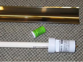
A T5 tube with a QEB
Glossary
Luminous efficacy: Luminous efficacy represents the light output (in lumen, lm) that the lamp can produce per unit of power input.